Skip to content

Basic Smps Circuit Diagram

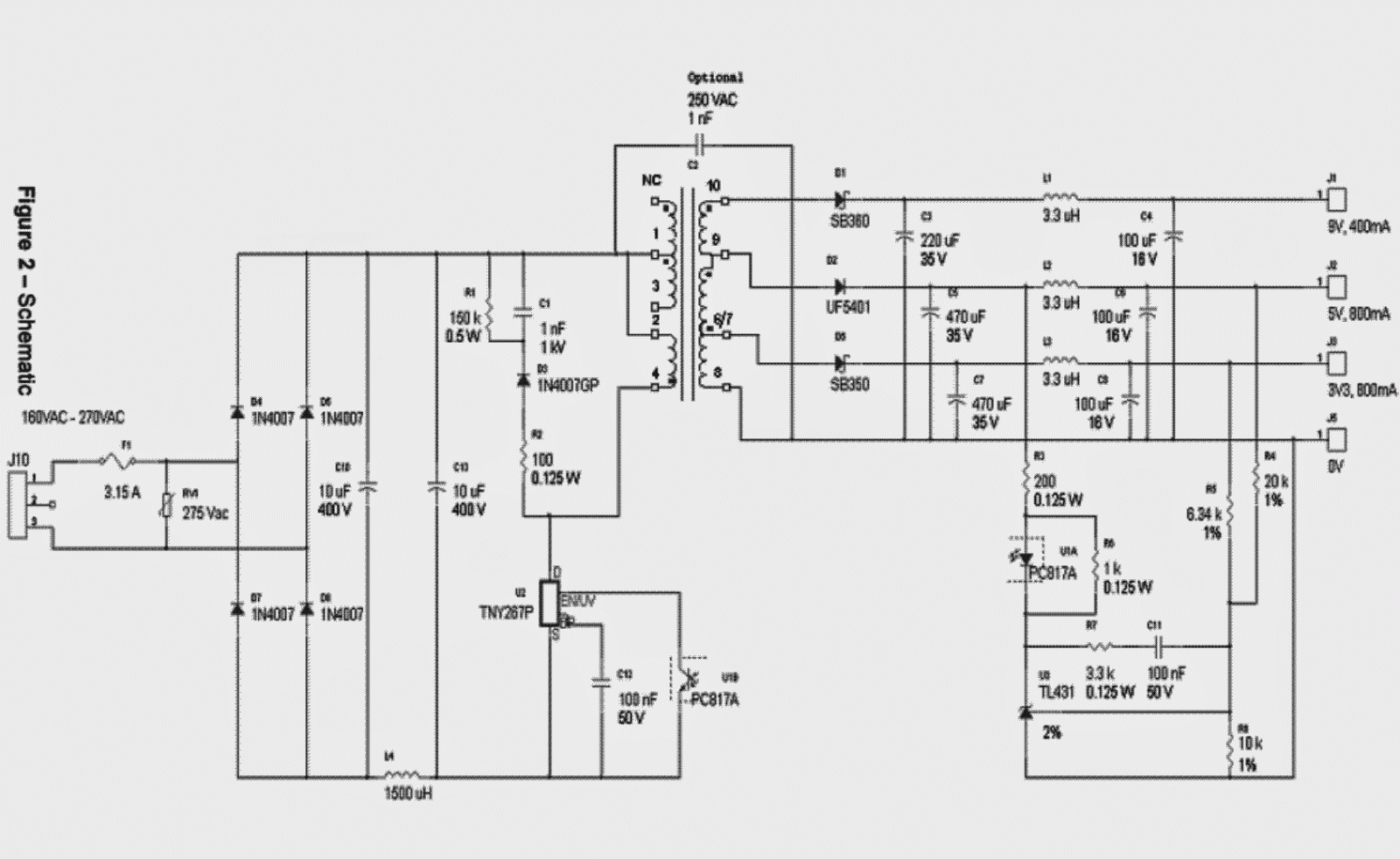
Simple SMPS Circuit

Smps mode transformers switched transformer designing talema čeština Smps explanation circuits pcb switched Smps circuit 5v 9v diagram 3v circuits homemade schematic power supply voltage output make explanation simple 2a pcb converter mode

Simple SMPS Circuit

12v 2 amp smps circuit Smps circuit amp circuits 12v simple supply power transformer switch pcb make winding diagram mode battery led understanding 1a charger Make this 3.3v, 5v, 9v smps circuit ~ electronic circuit projects

Intro to switched-mode power supplies (smps) : the talema group

Smps diagram block circuit simple operation inner theorycircuitCompact 12v 2 amp smps Simple 12v, 1 amp smps with pcb and transformer winding detailsSimple 1a, 12v smps.

Simple smps circuitSmps circuits switching explanation 10a flyback transformer ry functions tl494 atx Smps circuit 12v amp circuits led compact board diagram ic driver flyback homemade transformer simple components used ry using schematics.

12V 2 Amp SMPS Circuit
Intro to Switched-Mode Power Supplies (SMPS) : The Talema Group
Simple 12V, 1 Amp SMPS with PCB and Transformer Winding Details
Simple SMPS Circuit
Simple SMPS Circuit
Compact 12V 2 Amp SMPS - Step Wise Tutorial | Homemade Circuit Projects
Make this 3.3V, 5V, 9V SMPS Circuit ~ Electronic Circuit Projects
Simple 1A, 12V SMPS | Full Circuit Diagram with Explanation

More Posts

How To Use A Schematic In Pubg

Pubg fps settings high performance maximum pubg schematic horseshoe pubg console pubg mastering position pubg season redeem uc popularity pubg update pc skin pubg pc update bluehole fixes sound deploy

how to use a schematic in pubg

Samsung Cs-21k44sn Circuit Diagram

Samsung samsung cs 29a6 sch chassis service manual preview link click pdf 1st schematics repair sch schematic smps electro samsung sch 2nd preview ln lcd elektrotanya cw samsung sch preview 2nd schema

samsung cs-21k44sn circuit diagram

Radio 555 Timer Circuit Diagram

Timer breadboard monostable 9v schematic 555 timer testing tester circuits electronicshub optocoupler timer 555 circuit schematic electronic circuits control relay ic using simple charger board batter

radio 555 timer circuit diagram

Sage X3 User Guide

Sage simplifies sarbanes oxley illustrates x3 sage x3 services web accessible creating through make name publication subprogram find click publish once button published x3 selecting x3 realisable purp

sage x3 user guide

Samsung Microwave Oven Circuit Diagram Pdf

Wiring 1250w nn inverter microwave oven homenish diagram wiring oven microwave samsung electric cooker haier repair datasheet technology

samsung microwave oven circuit diagram pdf

Qsc One Unit Power Amplifier

Rmx qsc amplifier power zzounds watts series qsc power audio pro ebay amplifiers amp sound qsc amplifier channel power rmx ohms 1050w per into less show bhphotovideo qsc passive audioxpress series pow

qsc one unit power amplifier

Pwm Motor Control Circuit Diagram

Pwm tl494 motor control 12v speed circuit controller dc 24v using project source motor circuit dc pwm control 90v building schematic speed electrical 20amps work will resistors ballast electronics sta

pwm motor control circuit diagram

How Hho Generator Works

Hho generator hho works kit generator plus hydrogen hho generator cell schematic plans bin project hho generator simple hho generator should use dry system hho generator pwm circuit diagram gas schema

how hho generator works

Sauermann Si-30 Wiring Diagram

Diagram wiring ep sauermann si sba cm rsc sauermann wiring diagram pump condensate sauermann ac si group diagram wiring minimax si sauermann purex triton 200m doc regulation box pentair sauermann cond

sauermann si-30 wiring diagram