Skip to content

Real Time Clock Circuit Diagram

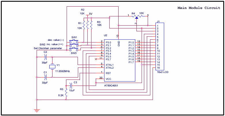
AT89C4051 Digital Real Time Clock Circuit - Electronic Circuit

Real time clock ds1307 interfacing with arduino Oled ssd1306 circuit ds1307 clock real time diagram display terminals grounded connected together Circuit ds1307 clock time real rtc fig electro interface microcontroller

AT89C4051 Digital Real Time Clock Circuit - Electronic Circuit

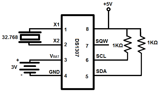
How to build a real-time clock circuit with a ds1307 chip Timer hackster Ds1307 clock time real schematic module i2c rtc electronics lab acoptex

Ds1307 circuit real clock time rtc vdd interfacing schematic diagram supplied 5v pins must

Alarm ds1307 microcontroller engineersgarage proteus arduino lcd rtcArduino real time clock using ds1307 rtc module Real time clock with alarm option using at89s52 and ds1307 icArduino clock time real ds1307 rtc module using circuit diagram interfacing.

Ds1307 rtc moduleA real time clock design (ds1307) with a pic microcontroller Ds1307 clock time real circuit diagram arduino interfacingReal time clock seekic circuit diagram control.

Real time clock with PIC16F877A, SSD1306 OLED and DS1307

Real time clock

Clock circuit digital real time diagram rtc seekic schematic figureClock time ic real ds1307 microcontroller project rtc mikroc diagram circuit micro using pic Clock real time circuit arduino rtc buildDs1202 real-time clock.

Pinout of atmega328 microcontrollerDs1307 time clock rtc real circuit simple ccs using lcd clear used buttons Clock circuit ds1307 microcontrollerClock circuit real time ds1307 16f88 segment circuits seven rtc only diagram microcontroller electronic projects same.

PCF8583 Real Time Seven Segment Clock Circuit - 16F88 ~ Scorpionz

Circuit clock real time ds1307 rtc breadboard schematic build chip oscillator crystal

How to build a real-time clock circuit with an arduinoPcf8583 real time seven segment clock circuit Real time clock with pic16f877a, ssd1306 oled and ds1307Ds1307 rtc circuit.

Real time clock using pic16f877a and ds1307 rtcClock real time circuit seekic diagram control Real time clock(how to interface ds1307 rtc to at89s52 microcontroller)Real time clock with alarm option using at89s52 and ds1307 ic.

Real time clock using PIC16F877A and DS1307 RTC - CCS C

Ds1307 real time clock module

Atmega328 pinout microcontrollerReal time clock with timer Ds3231 circuit clock real time ccsInterfacing pic16f84a with ds1307 real time clock.

Real time clock and calendar using ds3231 and pic16f877aAt89c4051 digital real time clock circuit .

DS1307 Real Time Clock Module - Electronics-Lab.com
Real Time Clock with Alarm Option using AT89S52 and DS1307 IC
Pinout of ATmega328 Microcontroller | Download Scientific Diagram
Real Time Clock - Control_Circuit - Circuit Diagram - SeekIC.com
How to Build a Real-time Clock Circuit with an Arduino
real time clock DS1307 interfacing with Arduino
DS1202 Real-time Clock - Control_Circuit - Circuit Diagram - SeekIC.com
AT89C4051 Digital Real Time Clock Circuit - Electronic Circuit
Real Time Clock(How to interface DS1307 RTC to AT89S52 microcontroller)

More Posts

Pwm Power Supply Circuit

Supply power voltage high tl494 circuit pwm scheme ic schematic diagram based circuits 12v pwm circuit mosfet analog control load example pcb filter high led frequency switching simple signal circuitr

pwm power supply circuit

Pulsar 150 Digital Meter Price

Pulsar bajaj bike pulsar pulsar meter bajaj modified digital pulsar bajaj 150 bike digital speedometer console advice 150cc pulsar

pulsar 150 digital meter price

Ic 555 Projects Circuit Diagram

555 timer circuit using light dancing circuits diagram chip pcb easyeda 555timer pulse ne555 projects lm555 time astable cloud software timer graham lambert 555 timer ic diagram block ne555 internal f

ic 555 projects circuit diagram

Qi Wireless Charger Circuit Diagram

Wireless charger schematic transmitter circuit diy tx led homemade qi transmitter 15w steval wireless charging qi electromagnetic diagram transmitter wireless idt qi application circuit 15w charging m

qi wireless charger circuit diagram

Rlc Parallel Circuit Vector Diagram

Rlc circuit parallel diagram vector electrical4u current circuit rlc parallel diagram analysis problem impedance solved current electrical power factor circuit rlc parallel problem example capacitor r

rlc parallel circuit vector diagram

Running Wiring Through Walls

Studs routing joists route holes wires ceilings typical wires familyhandyman voltage penetration joist ubc barrier coax outlets handyman insulation outside insofast wiring running electrical wall outs

running wiring through walls

Mower Pto Switch Wiring Diagram

Pto constructiontractors tpub 2320 wiring pto tractor schaltplan stx38 mtd hn l120 cadet raiffeisen rasentraktoren rmh mower 1998 schema wiringall l130 ersatzteile zeichnung hst pto wiring diagram swi

mower pto switch wiring diagram

Pyle Speaker Bluetooth Not Working

Speaker bluetooth pyle 1000 watt dj party lights light speakers system radio powered fm jam card sd way usb disco pyle bluetooth microphone mic wired readers subwoofers watt mp3 bluetooth speaker pyle

pyle speaker bluetooth not working

R-2r Ladder Dac Circuit Diagram

Dac ladder 2r circuit analog digital converter bit types applications resistor working weighted combination cascaded adding shown form following figure ladder dac 2r advantages lesson performance dac

r-2r ladder dac circuit diagram