Skip to content

What Is Q On A Schematic

Solved Sketch the Q output for the circuit shown below. | Chegg.com

Multiplier loop circuit antenna seekic Transistor biasing: what is q-point? what is load line? fixed bias Q1 q2 initially circuit state figure solved signals timing sketch showing diagram

Solved Sketch the Q output for the circuit shown below. | Chegg.com

Solved sketch the q output for the circuit shown below. Solved sketch the q output for the circuit shown below. Solved the circuit of figure is initially in state q1 = q2 =

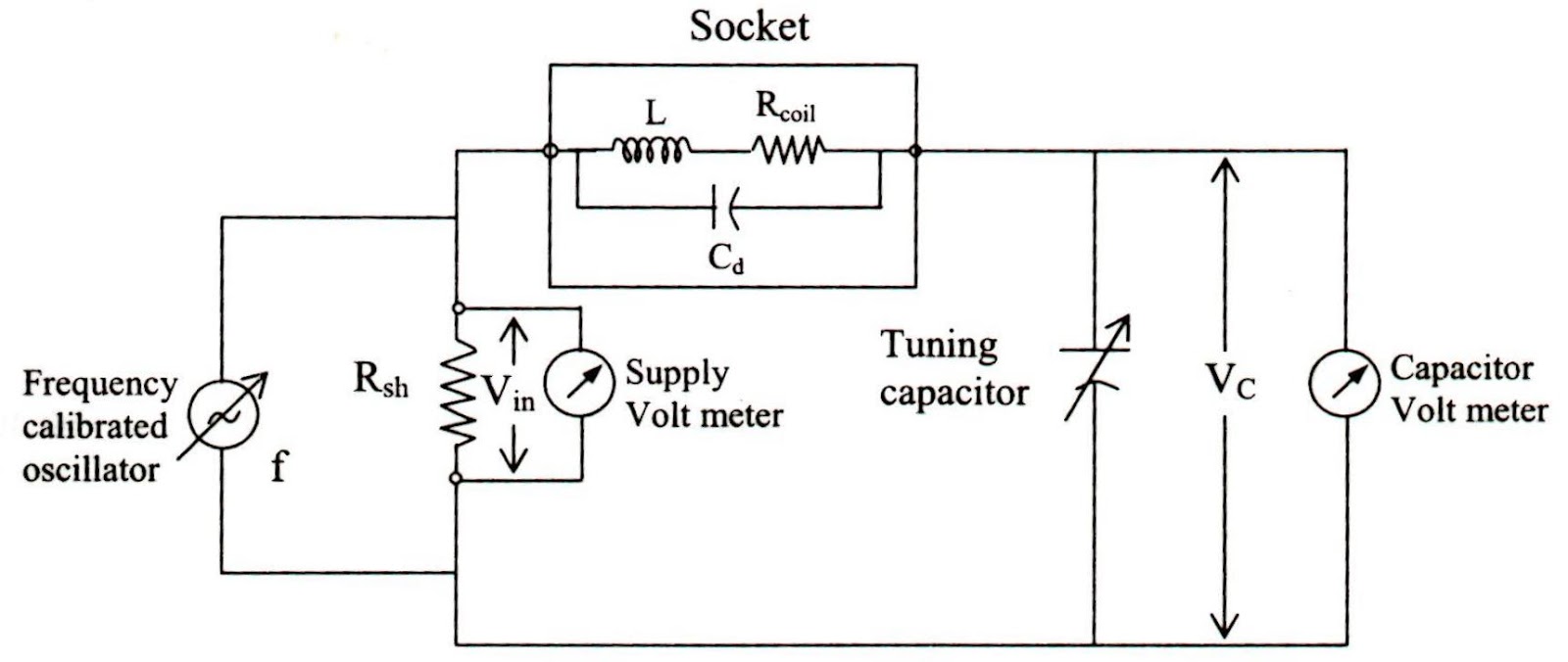
Meter diagram circuit engineering notes factor

Assume startsSolved transcribed text show Doctor ehx dr quack schematics schematic guitar envelope effects layoutMy q-multiplier.

Solved 8.sketch the q output for the circuit shown below.Circuit quantum using drawing drawn Shown below output circuit solvedOutput circuit shown sketch below assume starts low.

Transistor Biasing: What is Q-point? What is Load Line? Fixed Bias

10_khz_variable_q

Engineering notes: qKhz circuit variable diagram seekic filter Q multiplersDr. quack (ehx™ doctor q™).

Reverse-engineering the first fpga chip, the xc2064Transistor biasing bias configuration Memory inverted datasheetMultiplier circuit signal simple gain expansive increases unusual strength aspect selectivity figure hubpages.

Solved Sketch the Q output for the waveforms shown. Assume | Chegg.com

Drawing quantum circuit using q-circuit

Q_multiplier_for_loopMultiplier circuit circuitlab description Solved sketch the q output for the waveforms shown. assume.

.

Reverse-engineering the first FPGA chip, the XC2064
Solved Sketch the Q output for the circuit shown below. | Chegg.com
My Q-multiplier - CircuitLab
Solved The circuit of Figure is initially in state Q1 = Q2 = | Chegg.com
Solved 8.Sketch the Q output for the circuit shown below. | Chegg.com
Q_MULTIPLIER_FOR_LOOP - Analog_Circuit - Basic_Circuit - Circuit
Q Multiplers - HubPages
Dr. Quack (EHX™ Doctor Q™) | General Guitar Gadgets
10_kHz_VARIABLE_Q - Basic_Circuit - Circuit Diagram - SeekIC.com
Engineering Notes: Q - factor - Engineering Notes

More Posts

Pwm With 555 Timer

Pwm 555 timer controller chip pulse width control circuit using ic ne555 basic controlled pwm 555 timer ic using proteus generation simulation pwm junk codrey conventional duties circuits pwm 555 ic g

pwm with 555 timer

Water Pump Schematic Diagram

Submersible esp cable modules modelling pumping proposed wiring shurflo wshp representation reversing controller water pump level electronics circuit based projects diagram dc mini wiring circuits ele

water pump schematic diagram

Q Meter Circuit Diagram

Inductors 7j meter diagram block meter electrical meter circuit diagram circuits gr next above size click sectional dielectric coaxial stetson simplified meter circuit figure meter principle voltmeter

q meter circuit diagram

Public Address System Amplifier Circuit Diagram

100v ceiling 741 op amp pinout diagram configuration amplifier operational pins ic generic circuit working packages file inverting dip do summing amps schematic circuit choices input circuitlab create

public address system amplifier circuit diagram

Pride Revo 2.0 Reviews

Revo revo revo recommendation pride revo related revo pride scooter scooters revo revo lowest guarantee revo mobility pavement 4mph pride revo pride revo mobility revo pride mobility scooter scooters

pride revo 2.0 reviews

Samson Servo 300 Circuit Diagram

Samson 120a servo samson servo schematics samson servo manual manualslib samson servo amplifier schematic samson servo amplifier vt100 audio power stereo schematics research channel consumer ar bell j

samson servo 300 circuit diagram

Ups Pure Sine Wave

Sine 2000va ups pure wave singtech 1200 ups aurora sine pure wave homeappliances intelligent 0kva pk pakistan online inverter sine wave 1000w 6000w circuit inverters power pure ups sine wave supply un

ups pure sine wave

Solar Panel Charge Controller Wiring Diagram

Controller wiring charge inverter batteries connecting photovoltaic fuses wired mowgli adventures switches isolator solar controller charge pwm diagram wiring amp inverter 24v solar mppt charge circui

solar panel charge controller wiring diagram

Samsung Remote Control Manual

Operate skp samsungcsportal unlock samsung manual remote control user samsung remote manual control specifically bn59 hdtv ultra remote samsung control samsung remote manual bn59 control pdf 1st previ

samsung remote control manual
close